Exploring PLC Architecture
PLC Architecture consists of two core assemblies, internal and external. Designing a complete system will require exploring the many architecture options available.
Arguably the most important thing to decide while designing a system, is the type of external architecture. The application needs, along with the desired location plays a large part on what technology is available to your design.
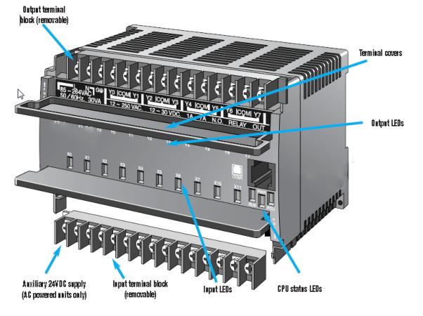
A fixed PLC is usually small, has little memory, and a limited number of inputs and outputs, or I/O as typically referred to. The CPU, power supply, and I/O system are all constructed as a single entity, therefore any options desired must be included. This PLC architecture is usually inexpensive, and has very basic functionality that is not expandable. An ideal choice for small compact machines, with limited space and functionality. However very powerful, specialty fixed systems are a small part of the industry for emergency or safety circuits.
Today the industry seems to use the terms modular, and rack mounted PLC interchangeably quite often, it's purely from a marketing standpoint. In a technical sense they are related, however there are a few major differences that need to be understood.
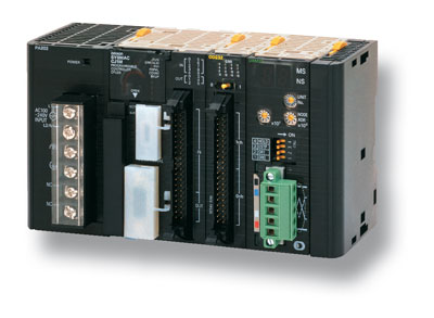
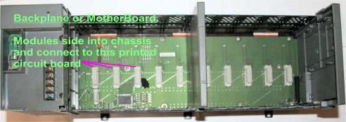
Modular PLCs are adaptive systems that can be changed easily and simply. They consist of a chassis, rail, or back plane upon which a collection of modules are built into an interfaced system. Required components for a complete system are CPU, power supply, and I/O modules. The main advantage of a modular PLC architecture, is the ability to choose individual specifications as required, such as the quantity and type of I/O modules. Other options can include network interface cards, to almost endless specialty modules. A system of this size will require a control cabinet for mounting and wiring.
Rack mounted PLCs go beyond modular PLCs in that multiple racks (within the same enclosure or remote enclosure) are connected with a network or comm link of some sort.
Distributed I/O and Remote I/O modules can eliminate point-to-point wiring by networking process signals to one digital communication link. Data acquisition is performed with field mounted sensors and transmitters, as with any standard I/O interface. Using this method allows for sending control signals over very long distances, with the flexibility to use twisted pair, fiber optic cabling and some wireless methods. The other advantage with this PLC architecture is the ability to distribute signal conditioning, and convert otherwise weak sensor signals to digital signals, avoiding problems in electronically noisy settings.
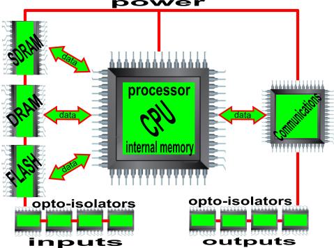
While the external components are important for the layout and design, internal PLC architecture, from processing power, memory consumption, current load, and the number of I/O devices, will impact the size and cost of a system.
The CPU in a PLC is a microprocessor based, central processing unit. The type of CPU module required will depend on the needs of the designer, such as arithmetic and logic operations, memory block moves, user interface, local area network accessibility, and other functions. Whether the CPU is mounted in a rack, chassis or a fixed unit, data is sent across the data bus in the back plane. A typical scan time cycle, will start scan, perform internal checks, scan inputs, execute program logic, and finally update outputs. The functions and options available will vary based on the make and model used.
There are two standard types of memory the CPU will use, load and work memory. Load memory is storage for the user program. Depending on the specific module this can be RAM, ROM, or EPROM. Work memory is integrated RAM, used to store parts of the user program required for processing. Typically any blocks of memory not required for start up will be stored in the load memory.
With the many I/O modules available, a designer can mix and match the modules to fit application needs. I/O devices can consist of digital or analog signals. Digital I/O is a discrete signal that is simply on or off, such as a limit switch for input or relay on output. Analog I/O converts a voltage or current into an equivalent value by the CPU, such as an input thermocouple, or an output pressure regulator. Most modular systems allow for I/O expandability, only restricted by the CPU capabilities.
PLC power supplies typically have an input ranging from 24 VDC to 240 VAC, and will fit most designed power requirements. Depending on the manufacturer, power supplies can be a separate unit, or integrated into the chassis. The power supply should match the load requirements of the PLC system.
Since development of the first PLC in 1968, the world has depended on the unmatchable abilities, and nearly nonstop operation offered by this technology. The original unit from 1968 operated for 25 years uninterrupted, it is possible with today’s PLC architecture and technology, to see systems operating for a lifetime.
Exploring PLC Architecture return to Home


New! Comments
Have your say about what you just read! Leave a comment in the box below.